Online Buying Store Product Details

{{image.AltTag}} {{image.AltTag}}
Default Image Default Image

{{details.product.ModelName}}

Sku: {{details.product.ModelNumber}}

Price: {{(details.product.BundleUnitCost || details.product.UnitCost) | currency : 'R' : 2}} (Excl. VAT)

Now: {{(details.product.BundleSalePrice || details.product.SalePrice) | currency : 'R' : 2}} (Excl. VAT)

The Picoscope 4424 and 4224 offer both a high resolution (12 bits) and a high DC accuracy (1%) making them an excellent choice for noise, vibration, precision electronics and mechanical analysis.
OUT OF STOCK, Contact office for lead time
Delivery time for this product is 5-7 business days
Please select an item in the list...
{{details.product.PriceUnits}}
Please fill out this field...
Please enter a number...
Please enter at least 1...
Please enter at max 999999...

You purchased this item on {{details.product.OrderHistory[0].OrderDate | date : 'yyyy-MM-dd'}}

Personal Greeting

12 bit oscilloscopes with optional IEPE interface

  • 2 or 4 channels
  • Optional IEPE interface (for accelerometers, microphones etc)
  • 12 bit resolution
  • 20 MHz bandwidth
  • 32 MS buffer memory
  • Serial decoding and mask testing as standard
  • USB connected and powered
  • Windows, Mac and Linux software

The Picoscope 4424 and 4224 offer both a high resolution (12 bits) and a high DC accuracy (1%) making them an excellent choice for noise, vibration, precision electronics and mechanical analysis.

The optional IEPE interface (see below) allows for the direct connection and powering of industry standard accelerometers and microphones.


High resolution offers 16x more detail

The PicoScope 4224 and 4424 are 12-bit oscilloscopes that offer 16 times more vertical resolution than traditional 8-bit oscilloscopes (4096 vertical levels vs 256). The example shows how with a 12-bit oscilloscope (blue trace) you can zoom in to reveal details of the signal that are not visible on an 8-bit oscilloscope (black trace).

As well as the high vertical resolution, the 32 million sample buffer memory ensures a high horizontal resolution as well. You can collect long detailed captures without the sampling rate dropping.

Once you have seen high-resolution waveforms on a high-resolution PC monitor you will never want to use a traditional benchtop oscilloscope with its small display again.

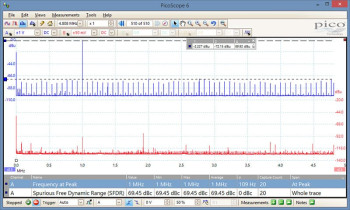
As well as improved oscilloscope traces, high resolution offers big benefits when performing spectrum analysis offering an additional 20 dB dynamic range on the spectrum over 8-bit oscilloscopes. Signals that were previously hidden in the noise floor are now clearly visible and the spectrum becomes a powerful tool to track down the causes of noise.


IEPE Interface

The PicoScope 4224 is available with an optional internal IEPE (integrated circuit piezoelectric) interface allowing for the direct connection and powering of industry standard accelerometers and microphones.  

When disabled the channels can be used as normal oscilloscope inputs. When IEPE is enabled (each channel has independent control via software) the input is AC coupled and a 24 V, 4 mA signal is output to power external sensors.

The high resolution and dynamic range of the 4224 makes it ideal for use with accelerometers and microphones. Having the IEPE interface built in makes for a compact, portable solution.


Advanced display

PicoScope software dedicates almost all of the display area to the waveform. This ensures that the maximum amount of data is seen at once. The viewing area is much bigger and of a higher resolution than with a traditional benchtop scope.

With a large display area available, you can also create a customizable split-screen display, and view multiple channels or different views of the same signal at the same time. As the example shows, the software can even show multiple oscilloscope and spectrum analyzer traces at once. Additionally, each waveform shown works with individual zoom, pan, and filter settings for ultimate flexibility.

The PicoScope software can be controlled by mouse, touchscreen or keyboard shortcuts.


FFT spectrum analyzer

FFT spectrum analyzer

The spectrum view plots amplitude vs frequency and is ideal for finding noise, crosstalk or distortion in signals. The spectrum analyzer in PicoScope is of the Fast Fourier Transform (FFT) type which, unlike a traditional swept spectrum analyzer, can display the spectrum of a single, non-repeating waveform.

A full range of settings gives you control over the number of spectrum bands (FFT bins), window types, scaling (including log/log) and display modes (instantaneous, average, or peak-hold).

You can display multiple spectrum views alongside oscilloscope views of the same data. A comprehensive set of automatic frequency-domain measurements can be added to the display, including THD, THD+N, SNR, SINAD and IMD. A mask limit test can be applied to a spectrum for automated testing.

More information on Spectrum analyzer >>


Picoscope 4424

Signal integrity

Most oscilloscopes are built down to a price. PicoScopes are built up to a specification.

Careful front-end design and shielding reduces noise, crosstalk and harmonic distortion. Years of oscilloscope design experience can be seen in improved bandwidth flatness and low distortion.

We are proud of the dynamic performance of our products and, unlike most oscilloscope manufacturers, we publish our specifications in detail. The result is simple: when you probe a circuit, you can trust in the waveform you see on the screen.


usb oscilloscope with IEPE interface

Portability

Pico Technology oscilloscopes are small, light and portable. In the lab they take up the minimum of bench space while for the engineer on the move they are small enough to fit in a bag with your laptop.

The USB connection makes printing, copying, saving, and emailing your data from the field quick and easy. The high-speed USB interface allows fast data transfer, while USB powering removes the need to carry around a bulky external power supply, making the scope even more portable for the engineer on the move.

The PicoScope 4424, 4224 and 4224 IEPE are supplied with software, documentation and USB cable. For the 4224 and 4424 a kit also containing oscilloscope probes and a carry case is available.

PicoScope 4224 & 4424 Features

Oscilloscope digital triggers

Advanced digital triggering

The majority of digital oscilloscopes still use an analog trigger architecture based on comparators. This causes time and amplitude errors that cannot always be calibrated out and often limits the trigger sensitivity at high bandwidths.

Over 20 years ago Pico first pioneered the use of fully digital triggering using the actual digitized data. This technique reduces trigger errors and allows our oscilloscopes to trigger on the smallest signals, even at the full bandwidth. Trigger levels and hysteresis can be set with high precision and resolution.

The PicoScope 4224 and 4424 offer industry-leading set of advanced triggers including pulse width, runt pulse, windowed, logic and dropout.

More information on Triggers, advanced >>


waveform buffer

Waveform buffer and navigator

Ever spotted a glitch on a waveform, but by the time you’ve stopped the scope it has gone? With PicoScope you no longer need to worry about missing glitches or other transient events. PicoScope can store the last ten thousand oscilloscope or spectrum waveforms in its circular waveform buffer.

The buffer navigator provides an efficient way of navigating and searching through waveforms, effectively letting you turn back time. Tools such as mask limit testing can also be used to scan through each waveform in the buffer looking for mask violations.

More information on Waveform buffer >>


PicoScope color persistence mode

Digital persistence modes

Advanced display modes allow you to collect thousands of waveforms per second. New or more frequent data can be displayed in a brighter color or shade. This makes it easy to see glitches and dropouts and to estimate their relative frequency. Choose between analog persistence, digital color, fast or custom display modes.

More information on Persistence modes >>


Oscilloscope mask limit test

The waveform buffer navigator can quickly highlight waveforms that fail the mask limit test


Mask limit testing

Mask limit testing allows you to compare live signals against known good signals, and is designed for production and debugging environments. Simply capture a known good signal, draw a mask around it, and then attach the system under test. PicoScope will check for mask violations and perform pass/fail testing, capture intermittent glitches, and can show a failure count and other statistics in the Measurements window.

More information on Mask limit testing >>


CAN bus serial decoding

Serial bus decoding and protocol analysis

PicoScope can decode 1-Wire, ARINC 429, CAN & CAN-FD, DCC, DMX512, Ethernet 10Base-T and 100Base-TX,  FlexRay, I²C, I²S, LIN, PS/2, MODBUS, SENT, SPI, UART (RS-232 / RS-422 / RS-485), and USB 1.1 protocol data as standard, with more protocols in development and available in the future with free-of-charge software upgrades.

Graph format shows the decoded data (in hex, binary, decimal or ASCII) in a data bus timing format, beneath the waveform on a common time axis, with error frames marked in red. These frames can be zoomed to investigate noise or signal integrity issues.

Table format shows a list of the decoded frames, including the data and all flags and identifiers. You can set up filtering conditions to display only the frames you are interested in or search for frames with specified properties. The statistics option reveals more detail about the physical layer such as frame times and voltage levels. PicoScope can also import a spreadsheet to decode the data into user-defined text strings.

More information on Serial bus decoding and protocol analysis - overview >>


High-end features as standard

Buying a PicoScope is not like making a purchase from other oscilloscope companies, where optional extras considerably increase the price. With our scopes, high-end features such as serial decoding, mask limit testing, advanced math channels and segmented memory are all included in the price.

To protect your investment, both the PC software and firmware inside the scope can be updated. Pico Technology have a long history of providing new features for free through software downloads. We deliver on our promises of future enhancements year after year, unlike many other companies in the field. Users of our products reward us by becoming lifelong customers and frequently recommending us to their colleagues.

PicoScope 4224 & 4424 Specifications

Oscilloscope — vertical
Model PicoScope 4424 PicoScope 4224 PicoScope 4224 IEPE
Passive probe mode IEPE interface mode
Input channels 4 2
Bandwidth DC to 20 MHz 1.6 Hz to 20 MHz
(10 MHz on ±50 mV range)
Rise time (10% to 90%, calculated) 17.5 ns (35 ns on ±50 mV range)
Input type Single-ended, BNC connector
Vertical resolution 12 bits
Enhanced vertical resolution 16 bits
Input sensitivity 10 mV/div to 20 V/div 10 mV/div to 4 V/div
Input ranges (full scale) ±50 mV to ±100 V in 11 ranges ±50 mV to ±20 V in 9 ranges
Input coupling Software-selectable AC/DC
Input characteristics 1 MΩ || 22 pF 1 MΩ || 1 nF
DC accuracy ±1%
Overvoltage protection ±200 V (DC + AC peak) ±100 V (DC + AC peak)
Oscilloscope — horizontal
Maximum sampling rate (single shot) 1 or 2 channels: 80 MS/s*
3 or 4 channels: 20 MS/s
80 MS/s
* To achieve the stated sampling rate with two channels, enable one channel from A or B and one from C or D.
Maximum sampling rate
(continuous streaming mode)
10 MS/s (Record length limited to 20 MS in PicoScope, unlimited when using the supplied SDK)
Timebase ranges 100 ns/div to 5000 s/div
Buffer memory 32 M  samples shared between active channels
Maximum buffer segments 10,000
Timebase accuracy 50 ppm with ≤10 ps jitter
Triggers
Source Any input channel
Trigger modes Free run, auto, repeat, single, rapid (segmented memory)
Trigger types Rising edge, falling edge, edge with hysteresis, pulse width, runt pulse, dropout, logic, windowed
Trigger level Adjustable over whole of selected voltage range
Trigger sensitivity Digital triggering provides 1 LSB accuracy up to full bandwidth.
Maximum pre-trigger capture 10 x “per division” timebase setting
Maximum post-trigger delay 50 s
Spectrum analyzer
Frequency range DC to 20 MHz
Display modes Magnitude, peak hold, average
Windowing functions Blackman, Gaussian, triangular, Hamming, Hann, Blackman–Harris, flat–top, rectangular
Number of FFT points Selectable from 128 to 1 million in powers of 2
Scale / units X axis : linear or log 10
Y axis : logarithmic (dbV, dBu, dBm, arbitrary) or linear (volts)
Math channels
Functions −x, x+y, x−y, x*y, x/y, x^y, sqrt, exp, ln, log, abs, norm, sign, sin, cos, tan, arcsin, arccos, arctan, sinh, cosh, tanh, freq, derivative, integral, min, max, average, peak, delay
Operands A, B (input channels), T (time), reference waveforms, constants, pi
Automatic measurements
Oscilloscope mode AC RMS, true RMS, cycle time, DC average, duty cycle, falling rate, fall time, frequency, high pulse width, low pulse width, maximum, minimum, peak to peak, rise time, rising rate.
Spectrum mode Frequency at peak, amplitude at peak, average amplitude at peak,
total power, THD %, THD dB, THD plus noise, SFDR, SINAD, SNR, IMD
Statistics Minimum, maximum, average and standard deviation
Serial decoding
Protocols 1-Wire, ARINC 429, CAN, DCC, DMX512, Ethernet (10Base-T), FlexRay, I²C, I²S, LIN, PS/2, SENT, SPI, UART/RS-232, USB 1.0
Inputs All input channels with any mixture of protocols
Mask limit testing
Mask generation Auto generate from captured waveform, manual drawing, manual coordinate entry
Actions Highlight on screen, select in buffer overview, activate alarm
Statistics Pass/fail, failure count, total count
Alarms
Initiating events Capture, buffer full, mask fail
Alarm actions Beep, play sound, stop/restart capture, run executable, save current buffer/all buffers, trigger signal generator
Display
Interpolation Linear or sin(x)/x
Persistence modes Digital color, analog intensity, fast, custom
Data export
Output file formats BMP, CSV, GIF, JPG, MATLAB 4, PDF, PNG, PicoScope data, PicoScope settings, TXT
Output functions Copy to clipboard, print
Environmental
Temperature range (operating) 0 °C to 45 °C
Temperature range (stated accuracy) 20 °C to 30 °C
Temperature range (storage) -20 to +60°C
Humidity range (operating) 5% to 80% RH, non–condensing
Humidity range (storage) 5 to 95% RH, non–condensing
Physical properties
Dimensions 200 x 140 x 35 mm (approx 7.9 x 5.5 x 1.4 in)
Weight <500 g (approx 1.1 lb)
PC requirements
Minimum Processor: 1 GHz
Memory: 512 MiB
Free disk space: 32–bit: 600 MB, 64–bit: 1.5 GB
Ports: USB 1.1 port (will result in significantly reduced performance)
Recommended Processor: 1 GHz
Memory: 512 MiB
Free disk space: 32–bit: 850 MB, 64–bit: 2 GB
Ports: USB 2.0 (or higher) port
Software
Windows software PicoScope for Windows
Software development kit (SDK)
Windows 7, 8 or 10 recommended (read more)
macOS software PicoScope for macOS (beta: feature list)
Software development kit (SDK)
OS versions: see release notes
Linux software PicoScope for Linux (beta: feature list)
Software development kit (SDK)
See Linux Software & Drivers for details of supported distributions
Languages Chinese (simplified), Chinese (traditional), Czech, Danish, Dutch, English, Finnish, French, German, Greek, Hungarian, Italian, Japanese, Korean, Norwegian, Polish, Portuguese, Romanian, Russian, Spanish, Swedish, Turkish
General
Additional hardware (supplied) USB 2.0 cable, user manuals
PC connectivity USB 2.0 port (compatible with USB 1.1 and USB 3.0; USB 1.1 not recommended)
Power requirements Powered from USB port
Safety approvals European LVD standard
EMC approvals European EMC standard
FCC Rules Part 15 Class A
Environmental approvals RoHS compliant
Total satisfaction guarantee In the event that this product does not fully meet your requirements you can return it for an exchange or refund. To claim, the product must be returned in good condition within 14 days.
Warranty 5 years

PicoScope 4224 & 4424 Manuals

Resource Language Version Size Updated
Data Sheets:
PicoScope 4000 Series Data Sheet English 12 3 MB January 04 2016
User’s Guides:
PicoScope 4000 Series User’s Guide English 7 2 MB December 09 2015
PicoScope 6 User’s Guide English 49 10 MB February 12 2018
Programmer’s Guides:
PicoScope 4000 Series Programmer’s Guide English 9 1 MB June 29 2016
Triggering a PicoScope signal generator using the PicoScope API functions English 1 54 KB April 01 2015
Quick Start Guides:
PicoScope USB Oscilloscope Quick Start Guide English
Français
Deutsch
Italiano
Español
中文 (简体)
한국어
日本語
20 4 MB June 11 2019
Training Guides:
PicoScope 6 Frequently Asked Questions English 4 949 KB April 08 2019
PicoScope 6 Oscilloscope Software Training Manual English 3 8 MB October 01 2014
Beginner’s Guide to PicoScope English 1 2 MB August 26 2014